1.0 Arduino für STM32 Überblick
Stoffverteilung entsprechend dem Bildungsplan Jahrgangsstufe 1 TGI Baden Württemberg.
NUCLEO L152RE
Synopsis: [stm32l152re-Überblick] [Referenz-Manual RM008] [Datenblatt stm32l152re] [API stm23duino] Beschafft bei reichelt.de
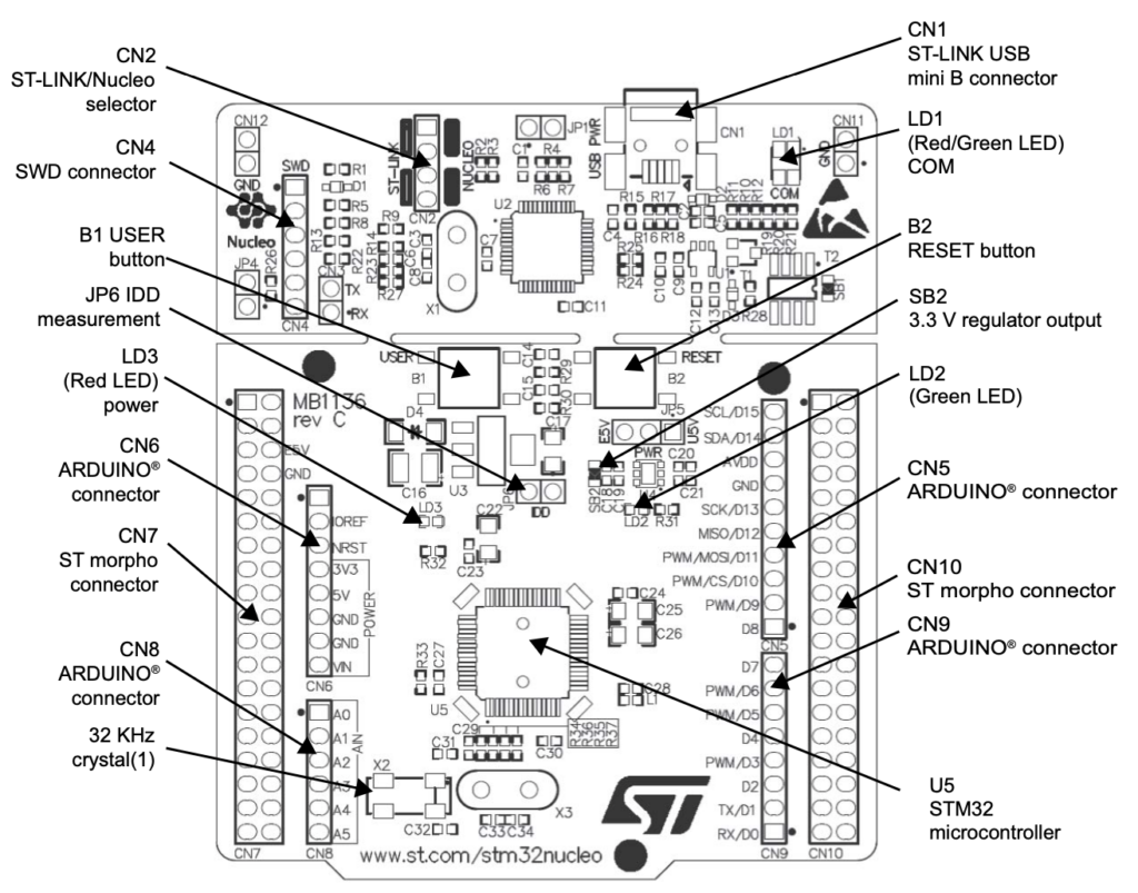
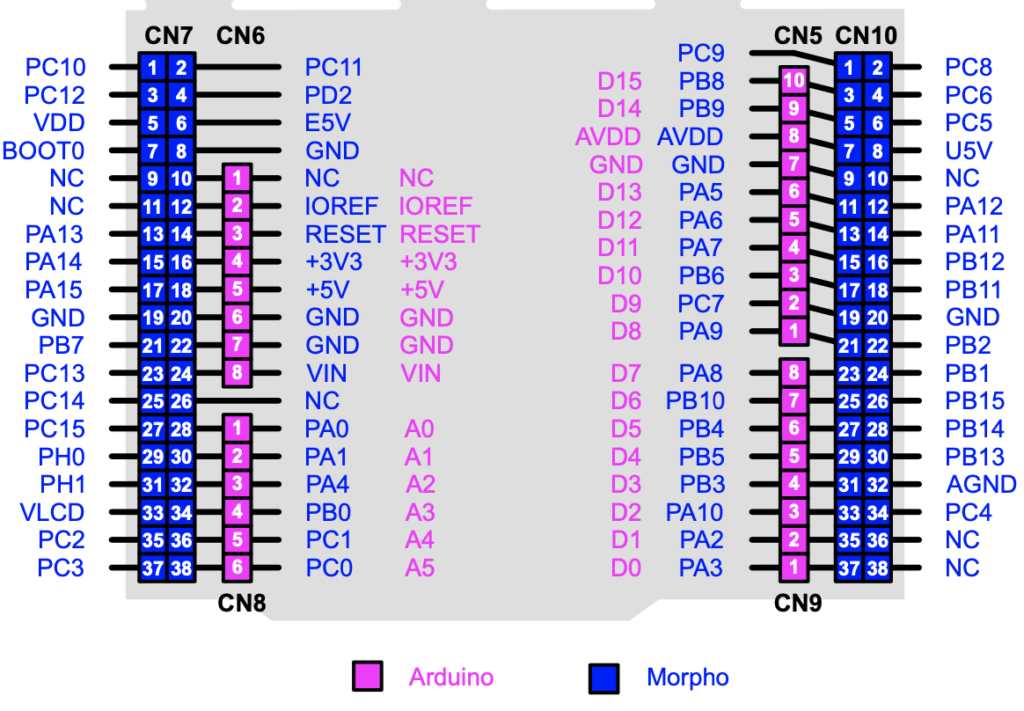
Pin Belegung
Grüne LED an PA5 (D13) , Blauer UserButton an PC13 mit PullUp-Widerstand und ist entprellt.

- Violett gekennzeichnet sind die PINs (mit ihrer Bezeichnung), die über die Arduino-Konnectoren nach nach außen gezogen sind.
- Blau gekennzeichnet sind die PINs (mit ihrer Bezeichnung), die nur über die STM-Konnectoren erreichbar sind.
- Gelb hinterlegt sind GPIO-Pins die software-seitig als analoger PIN definiert werden KÖNNEN
- Grau hinterlegt sind GPIO-Pins die auf dem Board nicht nach außen geführt sind
Mit analogWrite(Pin,Wert) können nur die 6 von Arduino vorgesehenen Pins verwendet werden.
| Aduino Pin | STM32 Pin |
|---|---|
| D3 | PB3 |
| D5 | PB4 |
| D6 | PB10 |
| D9 | PC7 |
| D10 | PB6 |
| D11 | PA7 |
Nucleo L152RE Pinbelegung
| Pin | Name | Arduino | Analog | Timer | I2C | SPI | U(S)ART | DAC |
|---|---|---|---|---|---|---|---|---|
| 2 | PC13 UserB | |||||||
| 3 | PC14 | |||||||
| 4 | PC15 | |||||||
| 5 | PH0 | |||||||
| 6 | PH1 | |||||||
| 8 | PC0 | A5 | ADC_IN10 | |||||
| 9 | PC1 | A4 | ADC_IN11 | |||||
| 10 | PC2 | ADC_IN12 | ||||||
| 11 | PC3 | ADC_IN13 | ||||||
| 14 | PA0 | A0 | ADC_IN0 | TIM2_CH1_ETR TIM5_CH1 | USART2_CTS | |||
| 15 | PA1 | A1 | ADC_IN1 | TIM2_CH2 TIM5_CH2 | USART2_RTS | |||
| 16 | PA2 | D1/TX | ADC_IN2 | TIM2_CH3 TIM5_CH3 TIM9_CH1 | USART2_TX | |||
| 17 | PA3 | D0/RX | ADC_IN3 | TIM2_CH4 TIM5_CH4 TIM9_CH2 | USART2_RX | |||
| 20 | PA4 | A2 | ADC_IN4 | SPI1_NSS SPI3_NSS | USART2_CK | DAC_OUT1 | ||
| 21 | PA5 LED | D13/SCK | ADC_IN5 | TIM2_CH1_ETR | SPI1_SCK | DAC_OUT2 | ||
| 22 | PA6 | D12/MISO | ADC_IN6 | TIM3_CH1 TIM10_CH1 | SPI1_MISO | |||
| 23 | PA7 | D11/MOSI/PWM | ADC_IN7 | TIM3_CH2 TIM11_CH1 | SPI1_MOSI | |||
| 24 | PC4 | ADC_IN14 | ||||||
| 25 | PC5 | ADC_IN15 | ||||||
| 26 | PB0 | A3 | ADC_IN8 | TIM3_CH3 | VREF_OUT | |||
| 27 | PB1 | ADC_IN9 | TIM3_CH4 | VREF_OUT | ||||
| 28 | PB2 | |||||||
| 29 | PB10 | D6/PWM | TIM2_CH3 | I2C2_SCL | USART3_TX | |||
| 30 | PB11 | TIM2_CH4 | I2C2_SDA | USART3_RX | ||||
| 33 | PB12 | ADC_IN18 | TIM10_CH1 | I2C2_SMBA | SPI2_NSS | USART3_CK | ||
| 34 | PB13 | ADC_IN19 | TIM9_CH1 | SPI2_SCK | USART3_CTS | |||
| 35 | PB14 | ADC_IN20 | TIM9_CH2 | SPI2_MISO | USART3_RTS | |||
| 36 | PB15 | ADC_IN21 | TIM11_CH1 | SPI2_MOSI | ||||
| 37 | PC6 | TIM3_CH1 | ||||||
| 38 | PC7 | D9/PWM | TIM3_CH2 | |||||
| 39 | PC8 | TIM3_CH3 | ||||||
| 40 | PC9 | TIM3_CH4 | ||||||
| 41 | PA8 | D7 | USART1_CK | |||||
| 42 | PA9 | D8 | USART1_TX | |||||
| 43 | PA10 | D2 | USART1_RX | |||||
| 44 | PA11 | SPI1_MISO | USART1_CTS | |||||
| 45 | PA12 | SPI1_MOSI | USART1_RTS | |||||
| 46 | PA13 | |||||||
| 49 | PA14 | |||||||
| 50 | PA15 | TIM2_CH1_ETR | SPI1_NSS SPI3_NSS | |||||
| 51 | PC10 | SPI3_SCK | USART3_TX UART4_TX | |||||
| 52 | PC11 | SPI3_MISO | USART3_RX UART4_RX | |||||
| 53 | PC12 | SPI3_MOSI | USART3_CK UART5_TX | |||||
| 54 | PD2 | TIM3_ETR | UART5_RX | |||||
| 55 | PB3 | D3/PWM | TIM2_CH2 | SPI1_SCK SPI3_SCK | ||||
| 56 | PB4 | D5/PWM | TIM3_CH1 | SPI1_MISO SPI3_MISO | ||||
| 57 | PB5 | D4 | TIM3_CH2 | I2C1_SMBA | SPI1_MOSI SPI3_MOSI | |||
| 58 | PB6 | D10/CS/PWM | TIM4_CH1 | I2C1_SCL | USART1_TX | |||
| 59 | PB7 | TIM4_CH2 | I2C1_SDA | USART1_RX | ||||
| 61 | PB8 | D15/SCL | TIM4_CH3 TIM10_CH1 | I2C1_SCL | ||||
| 62 | PB9 | D14/SDA | TIM4_CH4 TIM11_CH1 | I2C1_SDA |
Funduino Expansion Board für NUCLEO STM32
Entwickelt von Jörg Sturm, kostet bei Funduio.de 28,90€ pro Stück.
Link zum Produkt: [Funduino Expansion Board für NUCLEO STM32] Es wird noch ein NUCLEO-Board z.B. L152RE benötigt, ist nicht enthalten.
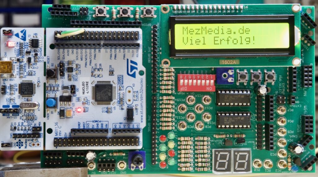
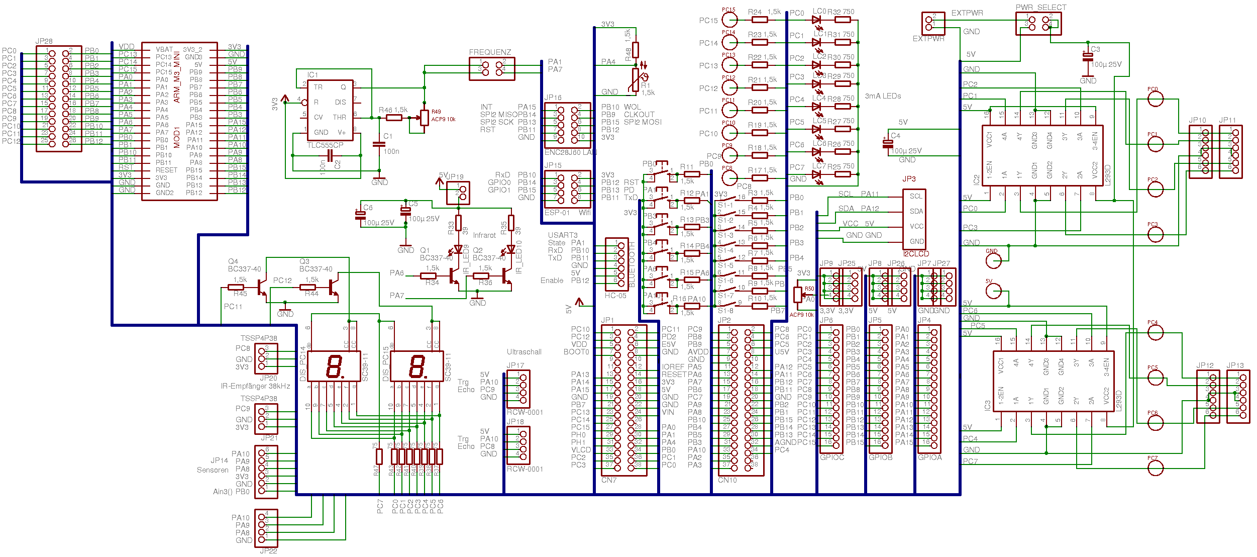
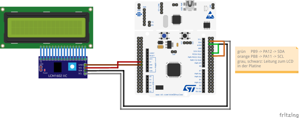
LCD-Ausgabe via I2C an Baseshield V1.2?
Das I2C-LCD-Display ist an PA11 (SCL) und PA12 (SDA) angeschlossen. Beim Assembler und bei MBED hat Herr Sturm eine Software I2C-Lösung zur Anbindung verwendet, d.h. es wird nicht die I2C-Hardware des Controllers genutzt, sondern die Schnittstelle ist per Software realisiert.
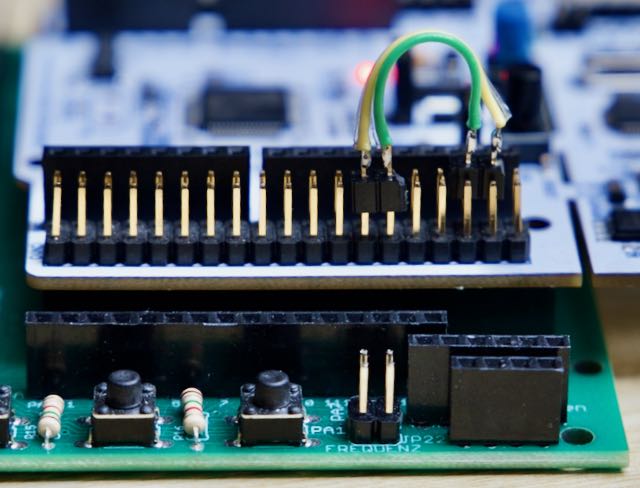
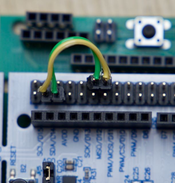
Die Arduino I2C-Library Wire benutzt standardmässig D15 = PB8 (SCL) und D14 = PB9 (SDA). Meine einfache Lösung sind zwei Drahtbrücken:
- Serial Clock SCL: D15 = PB8 -> PA11
- Serial Data SDA: D14 = PB9 -> PA12
#include <Wire.h> // Wire Bibliothek einbinden
#include <LiquidCrystal_PCF8574.h>
LiquidCrystal_PCF8574 lcd (0x27); // LCD-Adresse auf 0x27 für 16 Zeichen und 2 Zeilen ein

void setup() {
   lcd.begin(16, 2); // initialize the lcd
   lcd.clear();
   lcd.setBacklight(255);
   lcd.setCursor(0,0); // erstes Zeichen, erste Zeile
   lcd.print("MezMedia.de");
}

void loop() {
  delay(1000);
  lcd.setBacklight(255);
  lcd.setCursor(0,1); // erstes Zeichen, zweite Zeile
  lcd.print("Viel Erfolg!");
  delay(1000);
  for (int i= 255;i>=0;i--){
    lcd.setBacklight(i);
    lcd.setCursor(0, 1);
    lcd.printf("Backlight: %d    ",i);
    delay(50);
  }
}
Mit dem Testprogramm erkannt: Die Hintergrundbeleuchtung geht nur an und aus. 😕
Beim STM32L152RE gibt es zwei I2C Schnittstellen, die über eine interne Verdrahtungsmatrix auf unterschiedliche Ports geschaltet werden können. Im Datenblatt ab Seite 47 sind die möglichen Anschluss-Pins für I2C zu finden.
PA11 und PA12 sind leider nicht dabei. 😭
Nach der API-Beschreibung kann die zweite Schnittstelle recht leicht eingerichtet werden, auch dort könnte das LCD-Display mit Drahtbrücken von PB10 und PB11 angeschlossen werden. Leider wird dies mit der BlueTooth Schnittstelle kollidieren.
Oder ich krieg es mit einer Softwarelösung hin…
| Pin | I2C |
|---|---|
| PB5 (D4) | I2C1_SMBA |
| PB6 (D10) | I2C1_SCL |
| PB7 | I2C1_SDC |
| PB8 (D15) | I2C1_SCL |
| PB9 (D14) | I2C1_SDA |
| PB10 (D6) | I2C2_SCL |
| PB11 | I2C2_SDA |
| PB12 | I2C2_SMBA |
